How Does Screw Capping Work? Cap Feeding, Application, and Torque Control

Screw capping joins a threaded closure to a container so the package seals, survives handling and shipping, and can still be re-closed by the end-user. The result is not a matter of force alone. It depends on a short chain of controllable steps: getting the cap oriented, setting it straight on the neck, choosing a head that suits the closure, and applying a torque you can then verify.
This piece follows a single cap from a bulk supply to a tightened, checked seal. It covers cap feeding and orientation, placement on the container, the working difference between chuck and spindle heads, and how capping torque is applied, supported, and measured. It is about the mechanism; for how capping machines are grouped and chosen, see our guide to the types of capping machines.
How Are Caps Fed and Oriented?
Feeding converts a random bulk of caps into an oriented, single-file stream and releases one cap at a time in step with arriving containers.
The feeding and sorting workflow
An operator loads bulk caps into a hopper that acts as a buffer. A lift, often a cleated belt, carries them up to the orienter, which is the heart of the system: it sorts the randomly piled caps into a single-file line with the open side facing down. Gravity then carries the oriented caps down a chute to the capping station, where a gate releases one cap as each container arrives. Many heads add a “no bottle, no cap” sensor so a cap is only dropped when a container is present, which limits waste and jams.
Common orientation technologies
- Vibratory bowl feeders: vibration walks caps up a spiral track while tooling and air jets tip misaligned caps back into the bowl. They handle a wide range of caps and suit low-to-medium speeds.
- Centrifugal sorters: a spinning disc pushes caps outward, and rim tooling lets only correctly oriented caps leave, which suits continuous, higher-output lines.
- Elevator or waterfall sorters: cleats on an inclined belt carry seated caps to the top and let the rest fall back, combining lift and sort in one step.
- Wheel and pocket sorters: a rotating wheel with shaped pockets handles irregular closures such as trigger sprayers, dispensing spouts, and flip-tops that a bowl or disc cannot control.
Matching the sorter to the job
The choice comes down to the cap, the output you need, and how often you change formats. Simple flat screw caps are forgiving and fit almost any sorter; complex shapes such as T-caps, triggers, and pumps point to wheel or pocket designs. Higher speeds favor centrifugal and pocket units, while bowls offer a balance and usually change over with minor tooling tweaks. Realistic throughput depends on the specific machine, the cap, and the line, so a supplier sizes the feed from your samples and target rate rather than from a single headline number.
Feeding also has to keep pace without over-supplying. A hopper that runs low can starve the chute and let a container pass uncapped, while a gate that releases out of step with the line can drop a cap where no neck is waiting or feed two onto one. Steady hopper level, a chute kept clear, and a stop that reacts when the station backs up are what turn a rated sorter into a reliable flow.
How Is a Cap Placed on the Container?
Placement moves an oriented cap from the chute to sit squarely on the neck, so the threads can engage before tightening begins.
Delivery to the placement point
The oriented caps travel down a chute that holds their single-file alignment, ending just above the conveyor path. A sensor detects the approaching container and times the release of one cap. Getting this moment right is what keeps the cap centered as it lands.
Placement by machine type
The method follows the capper. Inline and spindle heads let the chute drop or gently set a cap as the container moves underneath. Rotary heads add a starwheel that indexes each container into position to pick up its cap. Chuck heads use a pick-and-place motion: the head lifts a cap from a presenter, travels over the neck, and sets it down before tightening. Each approach aims for the same end state, a cap resting flat and centered.
Seating, alignment, and the presence check
A light presser may settle the cap so it sits flat without crushing the threads, square enough to engage cleanly but loose enough for the head to turn it. Keeping the container vertical as the threads first meet is what reduces cross-threading and cocked caps. A downstream sensor then confirms a cap is present and positioned before the container proceeds; a missing or skewed cap can trigger a reject or a stop. A poorly timed placement is a leading cause of a weak seal, however well the torque is later controlled. The window is narrow: the cap has to be square and lightly seated so the threads start on their first lead, since a cap that begins crooked can cross-thread before the head applies any torque.
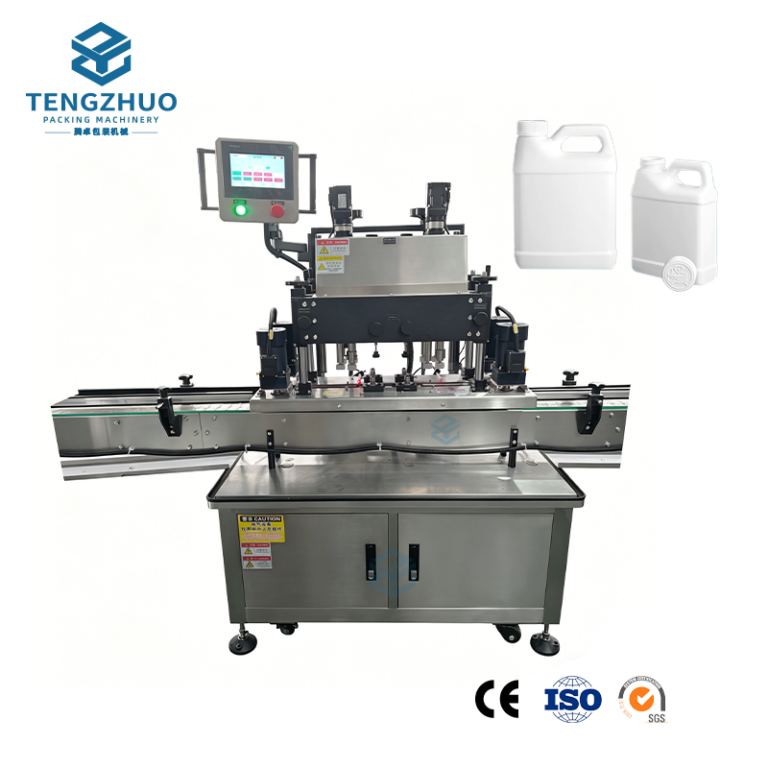
How Do Chuck and Spindle Capping Systems Differ?
Chuck heads grip the cap from the top; spindle heads tighten it with side friction wheels. The grip shapes the torque control, the cap appearance, and the changeover.
Grip and container motion
A chuck capper grips the cap from above, descends onto the container, tightens, and retracts. The container has to be restrained and kept in step with the head during the tighten, whether the machine holds each bottle in an indexed station or carries it through on a continuously moving rotary carousel. A spindle capper sets rotating friction wheels against the sides of the cap and tightens it while the container moves continuously past on the conveyor. That difference, stop-and-go versus run-through, is the root of most other trade-offs.
Torque control and cap appearance
Because a chuck drives the cap through a single head, it can hold a tight, repeatable torque with a clutch or servo, which matters for closures that need a documented value, such as child-resistant caps. Top-down contact also avoids scuffing the sidewall, so chucks tend to suit decorative or printed closures. A spindle applies torque by friction, so the delivered value can shift with cap material, wheel pressure, and wheel wear; that is workable for many general closures but leaves a wider tolerance, and the side contact can mark glossy or printed caps.
Speed and changeover
Continuous motion lets spindle heads run fast on a straight line and fit into most existing layouts, and they change over with simple adjustments to wheels and rails, which helps operations that switch SKUs often. Chuck heads reach high output mainly as large multi-head rotary machines, and each new format needs cap-specific parts such as chucks, inserts, and starwheels, so changeover is slower but the per-format performance is stronger. Actual figures depend on the machine size and container, so treat any single speed rating as a starting point, not a promise.
| Factor | Chuck capper | Spindle capper |
|---|---|---|
| Cap contact | Grips from the top | Friction wheels on the sides |
| Container motion | Pauses each cycle (indexed or rotary) | Runs continuously past the head |
| Torque control | Tight and repeatable via clutch or servo | Set by friction, wider tolerance |
| Cap appearance | Less sidewall marking | Can scuff glossy or printed caps |
| Changeover | Cap-specific change parts, slower | Wheel and rail adjustments, quicker |
| Typical fit | Specialty, CR, or appearance-critical caps | Standard screw caps, frequent changes |
How Is Capping Torque Applied, Supported, and Verified?
Torque is the rotational force the head puts into the cap. Controlling it needs three things: a firm drive, a steady container, and a way to check the result.
How the head applies torque
The capping head grips the cap and turns it down the container threads while grippers or belts hold the body still so it cannot spin with the cap. The head keeps turning until the cap is seated and reaches the set level of tightness.
Why container support matters
Most torque problems start below the cap. A bottle that slips, tilts, or lifts wastes the head’s energy, so readings drift and the liner compresses unevenly against the finish, which is how an apparently tight cap still leaks. Stable side support and, where needed, bottom handling keep the container vertical and still through tightening. This is most demanding with light or thin-walled bottles that can twist or collapse under force, and with containers that scuff against guide rails.
Clutches, servos, and the settings
Mechanical heads limit torque with magnetic or friction slip clutches preset to a value: once the tightening resistance passes that setting the clutch slips, so the drive can keep turning without adding more force and the cap is not pulled past the set torque. Servo-driven heads control torque, rotation speed, and often the angle of application electronically, so they hold a set value more consistently, and where the control package provides data logging they can also record each cycle. Clutch systems are simpler; servo systems give more control and traceability where the closure demands it.
Verifying with removal torque and inline checks
Applied torque is the primary setpoint during capping, but because it relaxes as materials settle, quality is usually confirmed after the fact by removal torque, the force needed to turn the cap back. Samples are tested after a conditioning period agreed for the closure, and removal torque sits below the application value by an amount that depends on the cap, liner, and storage. Test methods for this, such as ASTM D3198 for application and removal torque, define the setup and units so results stay comparable.
On the line, verification is layered. Vision checks confirm a cap is present and flag skewed, high, or cocked caps and an intact tamper band. Torque itself, however, is usually verified by sampling closures with a bench tester rather than measured on every container in line, since inline torque checks are not common. For products that must hold a pressure or hermetic seal, leak tests such as vacuum or pressure-decay challenge paths that vision cannot see. A reject at any stage removes the container so the line keeps running.
Away from the line, the same checks work as a routine. A practical routine is to sample removal torque at set intervals and after each changeover and read a drifting figure as a cue to inspect the clutch, wheels, or liner lot; recording applied torque per head helps where the machine exposes that signal, but many clutch heads do not report it. Because the value moves with material and temperature, a periodic record carries more weight than one setup reading.
What Causes Common Screw Capping Faults?
Most capping faults trace back to one of the steps above. Reading the symptom points you to the right place to look instead of adjusting the head at random.
- Cross-threaded or cocked cap: the cap met the neck at an angle. Check placement timing, container alignment, and worn guides before the capping head.
- Low or erratic torque: a drifting clutch, worn spindle wheels, or a container turning with the cap. Look at the head setting and the hold-down first.
- Over-torqued cap: a limit preset too high or stiff threads. Re-check the clutch or servo value and the finish tolerance.
- Scuffed or marked cap: side-wheel pressure on a printed or glossy closure. A chuck head or softer wheels reduce the contact mark.
- Liner not seated, then leaking: uneven compression from a lifted bottle or a mismatched liner. Verify container support and the liner-to-finish fit.
- Loose on arrival: torque decay from material relaxation, a low initial setting, or temperature swings. Confirm application torque and the liner choice.
Each symptom maps to a stage in this article: feeding decides whether a cap is there at all, placement decides whether it starts straight, and torque control and container support decide whether the seal holds. Working the chain in that order is faster than tuning the head on its own.
What Cap and Bottle Information Should Buyers Provide?
A supplier configures a capper from your components. Precise specs on both the cap and the bottle prevent fit and seal problems and avoid costly rework.
A vague note such as “a standard 28 mm cap” is not enough to set a machine. The practical way to scope a capping job is to hand over a complete technical package covering four areas.
Component identification and drawings
- Bottle and cap suppliers, part numbers, and materials (for example PET, HDPE, or glass).
- Controlled dimensional drawings for both parts, with revision levels.
- Surface finish, color, and any decoration that changes friction or handling.
Neck finish and thread specifications
- The standardized neck-finish code (for example 28-410) with its critical dimensions and tolerances.
- Thread profiles for the bottle neck and the internal cap threads.
- The sealing land where the liner compresses, plus any tamper-evident features.
Performance targets and production context
- Target application and removal torque ranges, in in-lb or N·m.
- Seal and leak criteria under the real storage and handling conditions.
- Target output and the planned feed method (manual or automatic).
- Product context that shapes the closure, such as viscosity, fill level, and chemical compatibility; the fill side is covered in choosing a filling machine.
Physical samples and compliance documents
Drawings define the ideal, but samples show the manufacturing reality. Provide enough bottles and caps, ideally spanning the tolerance band, so tooling and settings can be proven before a production run. Add any approved application specification for the combination and the compliance documents the market requires, such as food-contact or pharmaceutical-grade certificates for the materials. Sending this package up front is what turns a general capper into one set up for your closure, and it is far cheaper than uncovering a fit problem on the production line.
Foire aux questions
How does a screw capping machine work?
A screw capping machine feeds bottles and correctly oriented caps to a capping station, where a head, either a chuck or a set of spindle wheels, places the cap on the neck and applies controlled rotational torque to tighten it into a repeatable seal, after which the container moves on for labeling and packing.
What is the difference between chuck and spindle capping?
A chuck capper grips the top of the cap and turns it to a precise torque while the container pauses, which suits specialty and child-resistant closures and reduces sidewall marking. A spindle capper tightens the cap with side friction wheels as the container moves continuously, which is generally faster and easier to change over but gives a wider torque tolerance.
What is capping torque and how is it checked?
Capping torque is the rotational force used to tighten the cap, measured in inch-pounds (in-lb) or newton-meters (N·m). It is usually checked indirectly through removal torque, the force needed to turn the cap back after a conditioning period, following published methods such as those from ASTM International, and adjusted when results drift outside the set range.
Can one machine handle different cap sizes?
Often, yes. Many cappers cover a range of cap and bottle sizes through adjustable guide rails, head height, and wheel spacing, plus interchangeable change parts such as chucks or cap chutes. Spindle heads usually change over faster; chuck heads typically need cap-specific parts, so the practical range depends on the machine and the closures involved.
Why do screw caps become loose?
Caps can lose tightness through torque decay, a gradual drop in clamping force after application. Contributing factors include relaxation of the plastic in the cap and bottle, compression of the liner, temperature swings, and vibration in transit. An initial torque set too low can make the effect show up sooner.
Final Thoughts
Screw capping is a chain of small, controllable steps rather than a single forceful action. A reliable seal comes from matching the feeding, placement, and head type to your cap and container, holding a repeatable torque with a steady bottle, and then verifying the result instead of assuming it.
The practical next step is to define your cap, container, and output target precisely, then size the capping configuration to those facts. If you are weighing a screw capper for a specific line, the screw capping machines page is a good place to start the conversation.

Continue Reading
Explore more insights from our packaging machinery experts

Wrap-Around, Front-and-Back, and Flat-Surface Labeling Compared
Pressure-sensitive labeling splits by how the container moves and where the label datum sits. Compare the three methods, then send the samples a quotation needs.
Read Article
How Powder Flowability Affects Auger Filling
Air trapped between particles is why powders bridge, compact, and segregate. How flowability drives auger selection, testing, and what to send with an enquiry.
Read Article
Shrink Sleeve Defects: Wrinkles, Distortion, and Label Jams
Sleeve defects sort into four groups: shrink, position, feed, and heat damage. The evidence to collect before any tunnel or applicator setting gets changed.
Read ArticleReady to Upgrade Your Packaging Line?
Get in touch with our engineers for a free consultation and tailored equipment proposal within 24 heures.
Obtenez une conception de disposition de ligne CAO 3D gratuite
- Prix directs en usine
- Délai d'exécution rapide
- Composants mondiaux de premier plan
- Support après-vente dédié


